/ Agricultural equipment, equipment, inventory / Soil cultivation equipment / Cultivators / Cultivator KPS-4 (3-row)+spring-2-row+roller...
Sell / buy
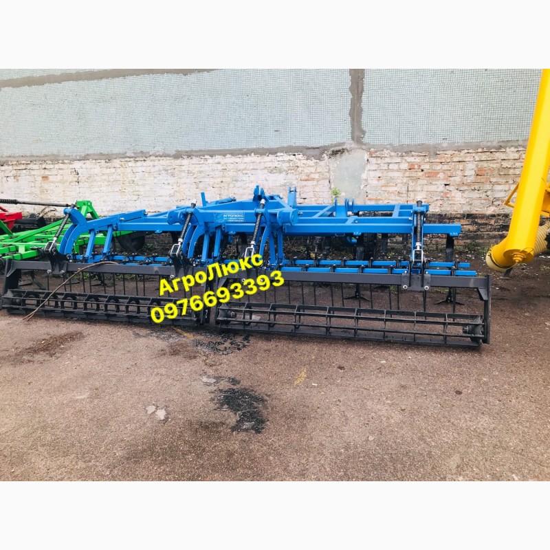
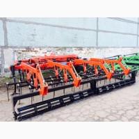
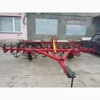
Cultivator KPS-4 (3-row)+spring-2-row+roller, reinforced, Kirovohrad region.
Price112 UAH.
Region:all Ukraine,
Kirovohradskaya region.
(Prospekt Inzhenerov 8)
Updated:
The above operations allow you to get optimal conditions for subsequent sowing. The design of the cultivator is a unit consisting of a central frame - the cultivator section, on which complete pawl working bodies are installed, a rear battery of 2-row spring-tooth harrows androllers, by means of rods attached to the rear beam of the frame. A hydraulic wheel mechanism is installed on the frame, providing both transportation and operation of the machine as supports, setting and maintaining the processing depth. The machine is connected to the power source (tractor) by means of a height-adjustable traction coupling device with a coupling loop at the end.
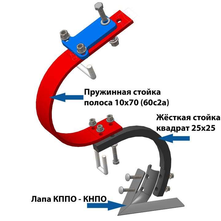
Working body of the KPPO cultivator Working body of the KPPO
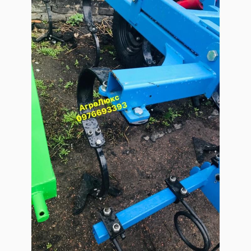
The working body consists of two "C"-shaped racks and an arrow paw with a grip width of 270 mm.
spring rack made of strip 10x70 (steel 60s2A)
Rigid rack made of a square 25x25
The paws are arranged in 4 rows in such a way that the minimum distance between adjacent ones in a row is 650 mm, between rows - 480 mm, between adjacent ones in the plan - 210 mm, which provides an overlap of 60 mm with a working width of the paw of 270 mm.
The spring-tooth harrow consists of a two-beam frame, on which teeth are installed in 2 rows with a pitch of 250 mm, with an offset of 125 mm. The frame is suspended on 4 leashes on rods and fixed with a limit chain. allowing unimpeded climbing up from the given level of travel.(//tractor-service.com)
Plate (ribbed) rollersrollers 255 mm are attached to two rods through an adjustable safety-pressure mechanism, which sets the required depth of travel, the pressure of the roller on the soil.
cultivator paw KPPO KNPO Paw KPPO-KNPO
The hydraulic wheel mechanism is designed in such a way that the hydraulic cylinder rod occupies two extreme positions:
Fully extended - transport position with a clearance of at least 300 mm.
Fully retracted - working position
The adjustment of the depth of movement of the paw working bodies is achieved by turning the wheel bracket around the axis to the required angle by lengthening or shortening the screw ties. One side of the lanyard is attached to the upper point of the cheek of the wheel mechanism, and the other side is attached to the bracket welded to the front beam of the frame. Shortening the lanyard leads to the lowering of the wheels and a decrease in the tread depth of the legs. The lengthening of the laces, on the contrary, leads to deepening of the paws.
One-wheeled mechanisms are installed on the central frame, which ensure high transport stability and reliable copying of the terrain and the required depth of processing.
Working body of the KPPO cultivator Working body of the KPPO
The working body consists of two "C"-shaped racks and an arrow paw with a grip width of 270 mm.
spring rack made of strip 10x70 (steel 60s2A)
Rigid rack made of a square 25x25
The paws are arranged in 4 rows in such a way that the minimum distance between adjacent ones in a row is 650 mm, between rows - 480 mm, between adjacent ones in the plan - 210 mm, which provides an overlap of 60 mm with a working width of the paw of 270 mm.
The spring-tooth harrow consists of a two-beam frame, on which teeth are installed in 2 rows with a pitch of 250 mm, with an offset of 125 mm. The frame is suspended on 4 leashes on rods and fixed with a limit chain. allowing unimpeded climbing up from the given level of travel.(//tractor-service.com)
Plate (ribbed) rollersrollers 255 mm are attached to two rods through an adjustable safety-pressure mechanism, which sets the required depth of travel, the pressure of the roller on the soil.
cultivator paw KPPO KNPO Paw KPPO-KNPO
The hydraulic wheel mechanism is designed in such a way that the hydraulic cylinder rod occupies two extreme positions:
Fully extended - transport position with a clearance of at least 300 mm.
Fully retracted - working position
The adjustment of the depth of movement of the paw working bodies is achieved by turning the wheel bracket around the axis to the required angle by lengthening or shortening the screw ties. One side of the lanyard is attached to the upper point of the cheek of the wheel mechanism, and the other side is attached to the bracket welded to the front beam of the frame. Shortening the lanyard leads to the lowering of the wheels and a decrease in the tread depth of the legs. The lengthening of the laces, on the contrary, leads to deepening of the paws.
One-wheeled mechanisms are installed on the central frame, which ensure high transport stability and reliable copying of the terrain and the required depth of processing.
|
Shop, contacts | |
AgroLux / отзывы, информация. / evaluation activities | |
|
Phone:
0976xxxxxx
show
| |
All user ads ~393 | |
Ad ID: #910523
(added by a registered user, registration date: 23-01-2016)
Added/Updated: 10-09-2026 11:30 (relevant, until: 10-09-2027)
Permanent ad address:
Showed / watched for today: ?, total: ?
Similar ads
Among them there are many interesting...

All Ukraine: Agricultural equipment, equipment, inventory 45592 / Soil cultivation equipment 5476 / Cultivators 1610
Kirovohrad region: Agricultural equipment, equipment, inventory 1794 / Soil cultivation technics 365 / Cultivators 135