/ Agricultural machinery, equipment, inventory / Spare parts for agricultural machinery / Spare parts for various s.g. equipment + in assortment / Driven clutch disc Zyl-130 rubber damper...

Sell / buy
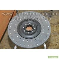
Driven clutch disc Zyl-130 rubber damper 130, Kharkiv region region.
Price520 UAH.
Region:
Kharkiv region.
Updated:
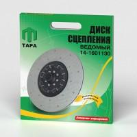
Driven clutch disc Zyl-130 rubber damper
Description
Driven clutch disc on a ZIL-130 vehicle
(damper on rubber bands)
130-1601130-A7
New from the factory, warranty, box, documents, delivery to any city in Ukraine.
The ZIL-130 clutch (Fig. 37) is a single-disc dry one installed in a cast iron housing 7. The clutch cover 9 is fixed to the flywheel 2 of the crankshaft 1 with eight centering (special) bolts 23. The clutch pressure is created by sixteen springs installed between the clutch cover 9 and the ZIL-130 clutch pressure disc 3. Heat-insulating washers are placed under the springs on the side of the pressure disk. The transmission of the torque from the clutch housing 9 to the driven disc is carried out through the pressure disc 3 by four pairs of spring plates 4.
The switch-off device consists of four levers 16, which are connected by fingers 20 to the pressure disc and fork 18. Between the fingers 20 and the lever 16, needle rollers 22 are placed. During the operation of the car, the position of these levers is not regulated.
[Clutch ZIL-130]
Fig. 37. Clutch ZIL-130:(//tractor-service.com)
1 — crankshaft: 2 — flywheel; 3 — pressure disk; 4— spring plate; 5 — sleeve of spring plates; 6 — plate fastening bolt; 7 — crankcase; 8 — compression spring; 9 — casing; 10 — heat-insulating washer of the compression spring; 11 — thrust bearing; 12 — coupling; 13 — tension spring of the clutch; 11 — guide clutch; 15 — clutch release plug; 16 — clutch release lever; 17 — adjusting nut; 18— plug; 19 — support plate of the adjusting nut; 20 - fingers; 21 - crankcase cover; 22 — rollers; 23 — a bolt for fastening the clutch cover to the flywheel; 24 — cotter pin; 25 — crown of the flywheel; 26 — driven disk; 27 — shield; 28 - drive shaft of the gearbox; 29 — drive shaft bearing.
The driven disc of the ZIL-130 clutch is steel, with friction linings, and has a torsional oscillating damper (damper) of the friction type (with dry friction of steel on steel). The elastic coupling of the damper consists of eight evenly spaced springs 2 (Fig. 38)
The driven disk is balanced. Balancing is carried out by installing balancing plates 10 on the driven disk.
[Clutch disc ZIL-130]
Fig. 38. Driven clutch disc ZIL-130:
1 - driven disk; 2 — spring of torsional oscillating damper (damper); 3 — support plate; 4 — oil reflector; 5 — damper disk; 6 — driven disc hub; 7 — rivet; 8 — fractional cover of the extinguisher; 9 — friction overlay of the driven disk; 10 — balancing plate.
To disengage the ZIL-130 clutch, a thrust bearing 11 (see Fig. 37) installed on the clutch 12 of the bearing is used. In bearing 11, the lubricant is placed at the factory and is not added during operation and repair. In the process of repairing the clutch, if necessary, the bearing should be replaced with a new one. With a correctly adjusted clutch drive, the gap between lever 16 and the clutch release bearing should be 3 — 4 mm.
To turn off the clutch, a pedal is used, the shaft of which is installed in a bracket fixed on the left side member of the ZIL-130 car frame. The lower end of the lever 8 is connected by an adjustable rod 7 (Fig. 39) to the lever 9 of the clutch release fork. The stroke of the pedal is limited by a stop on the floor of the cabin.
Fig. 39. Clutch drive ZIL-130:
1 — pedal; 2 — spring; 3 — spherical nut; 4 — counter nut; 5 —grease pan for lubricating the bushings of the clutch release fork; 6 — shaft; 7 — traction; 8 — intermediate lever; 9 — clutch release fork lever; 10 - oil pan.
Description
Driven clutch disc on a ZIL-130 vehicle
(damper on rubber bands)
130-1601130-A7
New from the factory, warranty, box, documents, delivery to any city in Ukraine.
The ZIL-130 clutch (Fig. 37) is a single-disc dry one installed in a cast iron housing 7. The clutch cover 9 is fixed to the flywheel 2 of the crankshaft 1 with eight centering (special) bolts 23. The clutch pressure is created by sixteen springs installed between the clutch cover 9 and the ZIL-130 clutch pressure disc 3. Heat-insulating washers are placed under the springs on the side of the pressure disk. The transmission of the torque from the clutch housing 9 to the driven disc is carried out through the pressure disc 3 by four pairs of spring plates 4.
The switch-off device consists of four levers 16, which are connected by fingers 20 to the pressure disc and fork 18. Between the fingers 20 and the lever 16, needle rollers 22 are placed. During the operation of the car, the position of these levers is not regulated.
[Clutch ZIL-130]
Fig. 37. Clutch ZIL-130:(//tractor-service.com)
1 — crankshaft: 2 — flywheel; 3 — pressure disk; 4— spring plate; 5 — sleeve of spring plates; 6 — plate fastening bolt; 7 — crankcase; 8 — compression spring; 9 — casing; 10 — heat-insulating washer of the compression spring; 11 — thrust bearing; 12 — coupling; 13 — tension spring of the clutch; 11 — guide clutch; 15 — clutch release plug; 16 — clutch release lever; 17 — adjusting nut; 18— plug; 19 — support plate of the adjusting nut; 20 - fingers; 21 - crankcase cover; 22 — rollers; 23 — a bolt for fastening the clutch cover to the flywheel; 24 — cotter pin; 25 — crown of the flywheel; 26 — driven disk; 27 — shield; 28 - drive shaft of the gearbox; 29 — drive shaft bearing.
The driven disc of the ZIL-130 clutch is steel, with friction linings, and has a torsional oscillating damper (damper) of the friction type (with dry friction of steel on steel). The elastic coupling of the damper consists of eight evenly spaced springs 2 (Fig. 38)
The driven disk is balanced. Balancing is carried out by installing balancing plates 10 on the driven disk.
[Clutch disc ZIL-130]
Fig. 38. Driven clutch disc ZIL-130:
1 - driven disk; 2 — spring of torsional oscillating damper (damper); 3 — support plate; 4 — oil reflector; 5 — damper disk; 6 — driven disc hub; 7 — rivet; 8 — fractional cover of the extinguisher; 9 — friction overlay of the driven disk; 10 — balancing plate.
To disengage the ZIL-130 clutch, a thrust bearing 11 (see Fig. 37) installed on the clutch 12 of the bearing is used. In bearing 11, the lubricant is placed at the factory and is not added during operation and repair. In the process of repairing the clutch, if necessary, the bearing should be replaced with a new one. With a correctly adjusted clutch drive, the gap between lever 16 and the clutch release bearing should be 3 — 4 mm.
To turn off the clutch, a pedal is used, the shaft of which is installed in a bracket fixed on the left side member of the ZIL-130 car frame. The lower end of the lever 8 is connected by an adjustable rod 7 (Fig. 39) to the lever 9 of the clutch release fork. The stroke of the pedal is limited by a stop on the floor of the cabin.
Fig. 39. Clutch drive ZIL-130:
1 — pedal; 2 — spring; 3 — spherical nut; 4 — counter nut; 5 —grease pan for lubricating the bushings of the clutch release fork; 6 — shaft; 7 — traction; 8 — intermediate lever; 9 — clutch release fork lever; 10 - oil pan.
|
Author, contacts | |
Oleg Sergeevich Dolgov / reviews, info. / evaluation of activity | |
|
Phone:
(067xxxxxx
show
| |
All user ads ~1000 | |
Ad ID: #480577
(added by a registered user, registration date: 03-03-2012)
Added / Updated: 09-21-2026 10:16 (current, until: 09-21-2027)
Permanent Ad Address:
Impressions / views for today: ?, total: ?
Similar ads
There are many interesting ones among them...
Total18347 similar adsin the section "Spare parts for agricultural machinery"